

I currently have the Spectra Fuel Sending Unit (SU) that was installed about 4 years ago while on the Road/Vacation. While installing the Racetronix FP Kit and Intank Harness, I noticed some issues with the Spectra SU…..
1) The ground wire going to the bulkhead fitting was under sized.
2) The Fuel Gauge Wire (Blue) was soldered directly to the Resistor Board.
3) Refurbishing the SU Float Resistor is different on these.
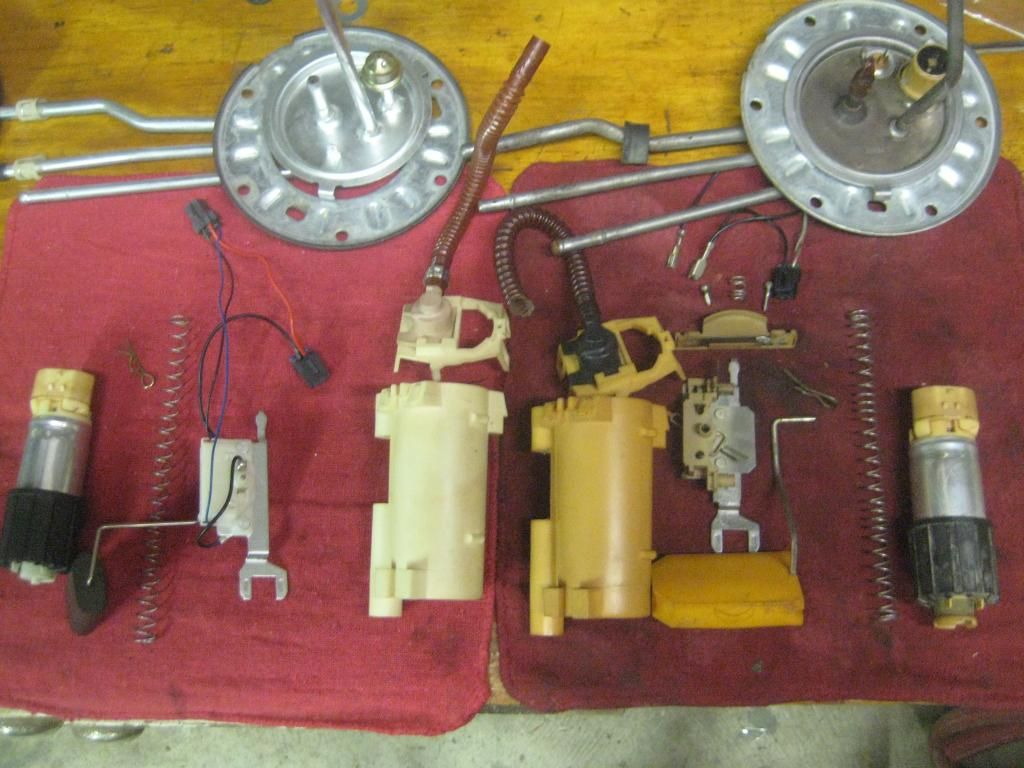
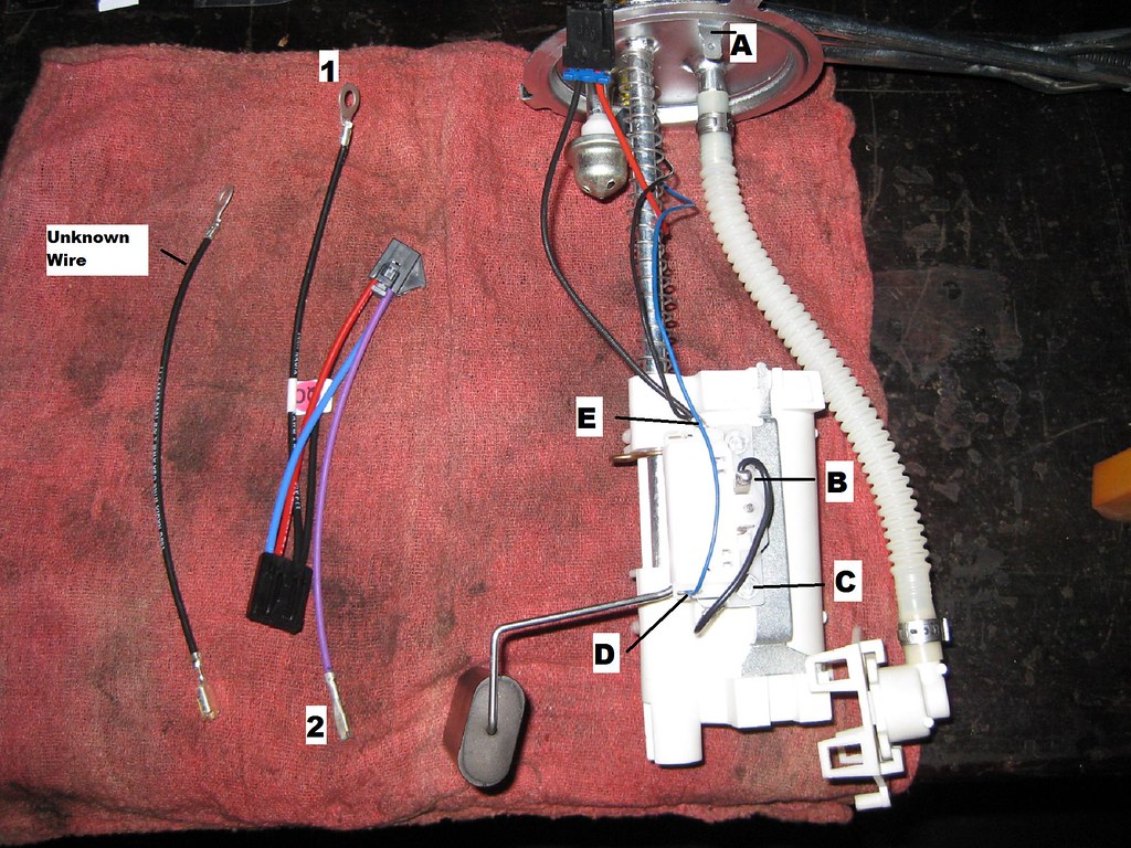
I also have a spare GM Sending unit that has a damaged metal tube that I was going to use for parts. With the exception of the Wiring to the Resistor Board for the Float Assembly, both the GM and Spectra SU’s share similar parts and they can be used across both units. This pic shows the 2 SU’s broken down into all their pieces with the GM unit on the right.
![Image]()
I wanted to use the GM Float Assembly/resistor on the Spectra SU since it had connectors that matched the intank harness that was sent with the Racetronix kit. However, after following the process to “refurbish the Sending Unit” found in this thread...
http://www.impalassforum.com/vBulletin/showthread.php?t=235185&highlight=refurbish+sending+unit
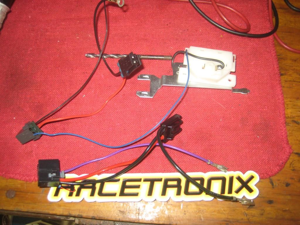
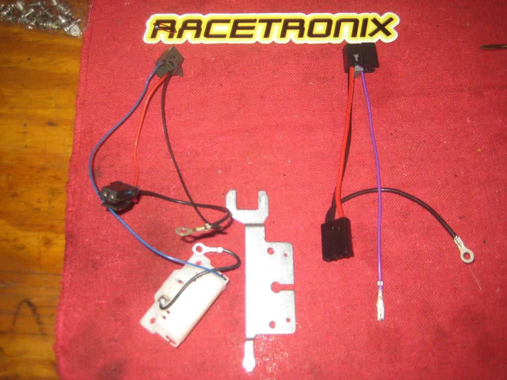
...I found that the ohm’s reading at full was only 82 ohms. With this reading the gas gauge on the cluster only registered about 8/10s Full with the Float at Full. After checking the Spectra Float level, I found that the Resistance reading was spot on for both Full and Empty and changed smoothly as the float was moved. The problem with using the Spectra Assembly is that the Racetronix Harness wont work unless its modified. Here is a pic of all 3 harnesses, Spectra on the Left, Racetronix in the Middle and the GM harness on the Right.
![Image]()
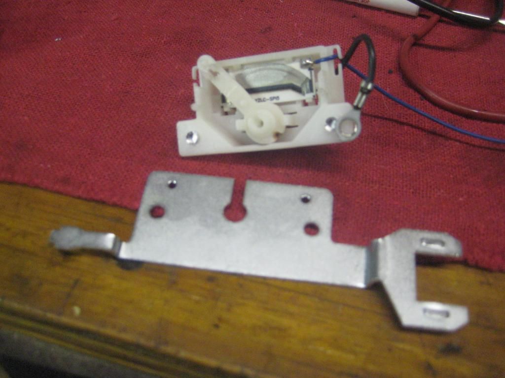
The other issue was that unlike the GM unit described in the “Refurb” thread, the Spectra unit is riveted together and has the 2 ground wires attached at the Rivets. If you wish to “refurb” this unit as well then you will need to drill out the rivets. I wanted to refurb it while I had things apart and decided that re-assembly with some stainless Screws would give a good point to anchor the ground wires. Here is the unit after I just drilled out the rivets and took it apart.
![Image]()
Once I removed the Plastic housing that contains the resistor board from the metal bracket, I was able to use similar cleaning methods described in the Refurb thread. Pic of it removed.
![Image]()
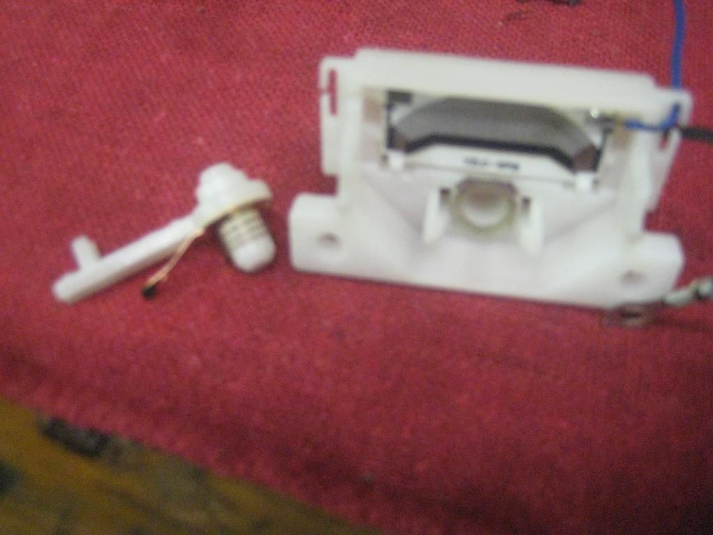
Once removed, you can then see how the swing arm for the float can be removed and like the GM unit, it also uses a spring to connect the circuit. I removed the Spring and cleaned all contact points of it as well as the housing.
![Image]()
As was mentioned, the Spectra unit has a tiny ground wire and does not use the Spade type terminals that the GM unit does. The racetronix harness is designed to work with the GM unit and a little modding was needed to get this to work with the Spectra Float Assembly.
Since the ground terminal of the Spectra SU was attached with a ring Terminal to the rivet, I decided to cut off the spade connector of the Racetronix harness and crimp on and Solder a Ring terminal instead. Here is a picture of the modified Racetronix Harness on the right.
![Image]()
As you can see the Purple wire on the Racetronix Harness is too short and also has a Spade Connector for the GM SU. Using a Safety Pin, I just removed this wire from the Plastic Bulk Head Connector of the Racetronix Harness. I then removed the Blue wire (why its Blue and not Purple I dunno) from the Spectra SU and installed it in the Racetronix Bulk Head Connector. The result can be seen in this pic with the Purple Wire not being used at all.
![Image]()
Once this was complete, I began to reassemble the Float Assembly using Stainless #8 ¾” 32 thread bolts and matching Nuts and washers. I used a flat washer on both sides along with a Lock Washer on the nut side and also doubled up 2 nuts on the end and tightened the nuts into each other as the German’s say “gudentite” to prevent them from backing off from vibration. I considered using Nylon topped nuts but was concerned they may dissolve being submersed in Gas. Here’s a couple pics of the Spectra float assembly put back together.
![Image]()
![Image]()
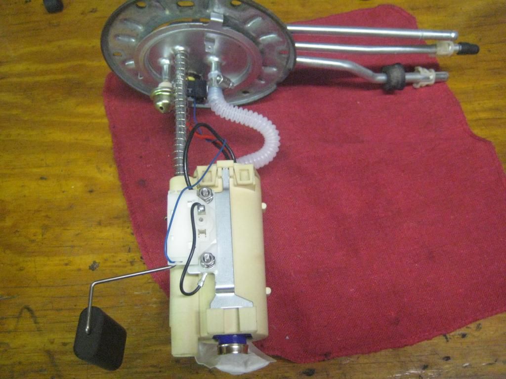
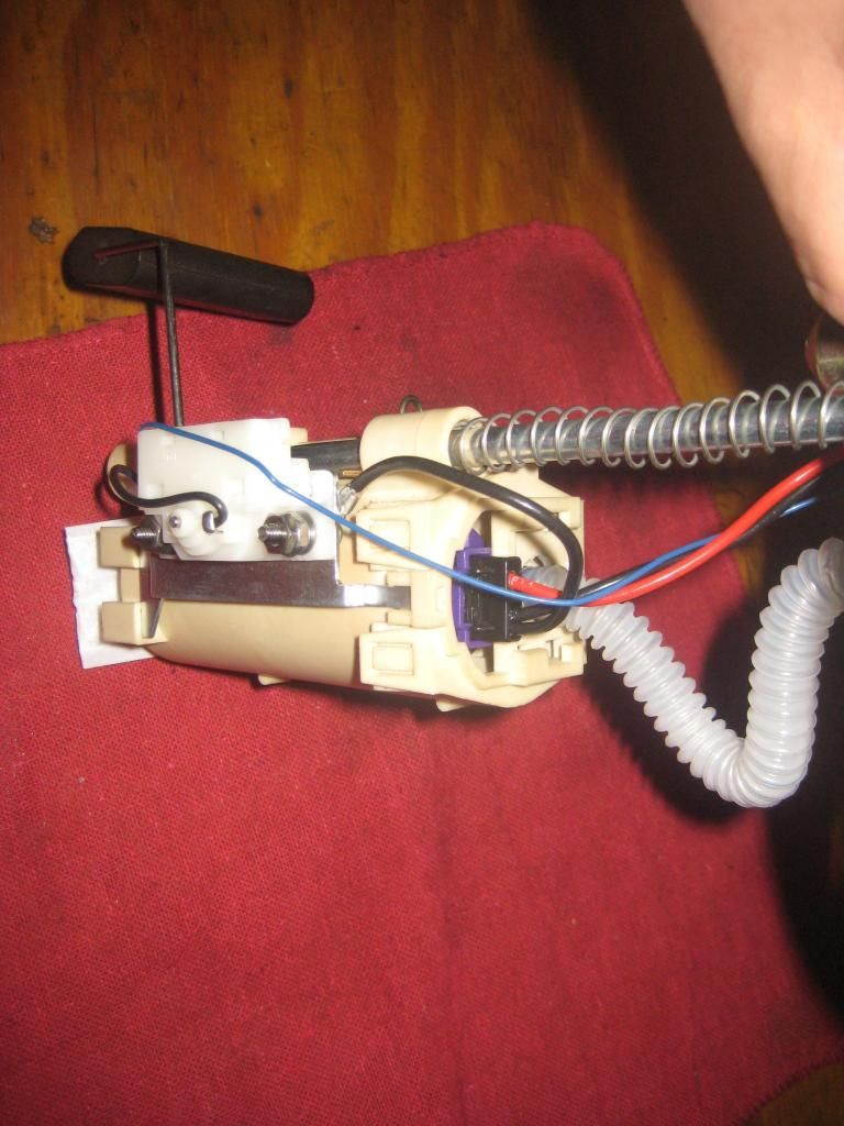
Once it was put back together, it was then mounted back to the Plastic Pump Housing and all was connected back up before installing back in the tank. As a test and before installing the SU/Fuel Pump assembly back in the tank, I connected the 3 wire harness and verified that the Cluster Gauge worked correctly and that I had good Ground and 12V to the Pump. A couple of pics of the whole unit before it went back in the tank
![Image]()
![Image]()
Hopefully this helps someone out that is also looking to replace their harness, FP or Refurbish the SU and has an aftermarket SU in the tank. I’m not certain, but I believe that GM has also changed their stock replacement part and it now uses a similar Float Assembly as the Spectra. So you may need to mod it in a similar fashion if using a stock type harness.
1) The ground wire going to the bulkhead fitting was under sized.
2) The Fuel Gauge Wire (Blue) was soldered directly to the Resistor Board.
3) Refurbishing the SU Float Resistor is different on these.
I also have a spare GM Sending unit that has a damaged metal tube that I was going to use for parts. With the exception of the Wiring to the Resistor Board for the Float Assembly, both the GM and Spectra SU’s share similar parts and they can be used across both units. This pic shows the 2 SU’s broken down into all their pieces with the GM unit on the right.
I wanted to use the GM Float Assembly/resistor on the Spectra SU since it had connectors that matched the intank harness that was sent with the Racetronix kit. However, after following the process to “refurbish the Sending Unit” found in this thread...
http://www.impalassforum.com/vBulletin/showthread.php?t=235185&highlight=refurbish+sending+unit
...I found that the ohm’s reading at full was only 82 ohms. With this reading the gas gauge on the cluster only registered about 8/10s Full with the Float at Full. After checking the Spectra Float level, I found that the Resistance reading was spot on for both Full and Empty and changed smoothly as the float was moved. The problem with using the Spectra Assembly is that the Racetronix Harness wont work unless its modified. Here is a pic of all 3 harnesses, Spectra on the Left, Racetronix in the Middle and the GM harness on the Right.

The other issue was that unlike the GM unit described in the “Refurb” thread, the Spectra unit is riveted together and has the 2 ground wires attached at the Rivets. If you wish to “refurb” this unit as well then you will need to drill out the rivets. I wanted to refurb it while I had things apart and decided that re-assembly with some stainless Screws would give a good point to anchor the ground wires. Here is the unit after I just drilled out the rivets and took it apart.
Once I removed the Plastic housing that contains the resistor board from the metal bracket, I was able to use similar cleaning methods described in the Refurb thread. Pic of it removed.
Once removed, you can then see how the swing arm for the float can be removed and like the GM unit, it also uses a spring to connect the circuit. I removed the Spring and cleaned all contact points of it as well as the housing.
As was mentioned, the Spectra unit has a tiny ground wire and does not use the Spade type terminals that the GM unit does. The racetronix harness is designed to work with the GM unit and a little modding was needed to get this to work with the Spectra Float Assembly.
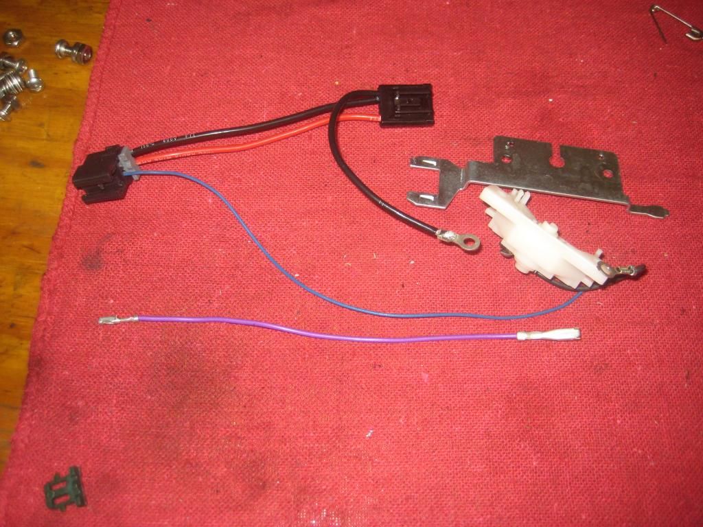
Since the ground terminal of the Spectra SU was attached with a ring Terminal to the rivet, I decided to cut off the spade connector of the Racetronix harness and crimp on and Solder a Ring terminal instead. Here is a picture of the modified Racetronix Harness on the right.
As you can see the Purple wire on the Racetronix Harness is too short and also has a Spade Connector for the GM SU. Using a Safety Pin, I just removed this wire from the Plastic Bulk Head Connector of the Racetronix Harness. I then removed the Blue wire (why its Blue and not Purple I dunno) from the Spectra SU and installed it in the Racetronix Bulk Head Connector. The result can be seen in this pic with the Purple Wire not being used at all.
Once this was complete, I began to reassemble the Float Assembly using Stainless #8 ¾” 32 thread bolts and matching Nuts and washers. I used a flat washer on both sides along with a Lock Washer on the nut side and also doubled up 2 nuts on the end and tightened the nuts into each other as the German’s say “gudentite” to prevent them from backing off from vibration. I considered using Nylon topped nuts but was concerned they may dissolve being submersed in Gas. Here’s a couple pics of the Spectra float assembly put back together.
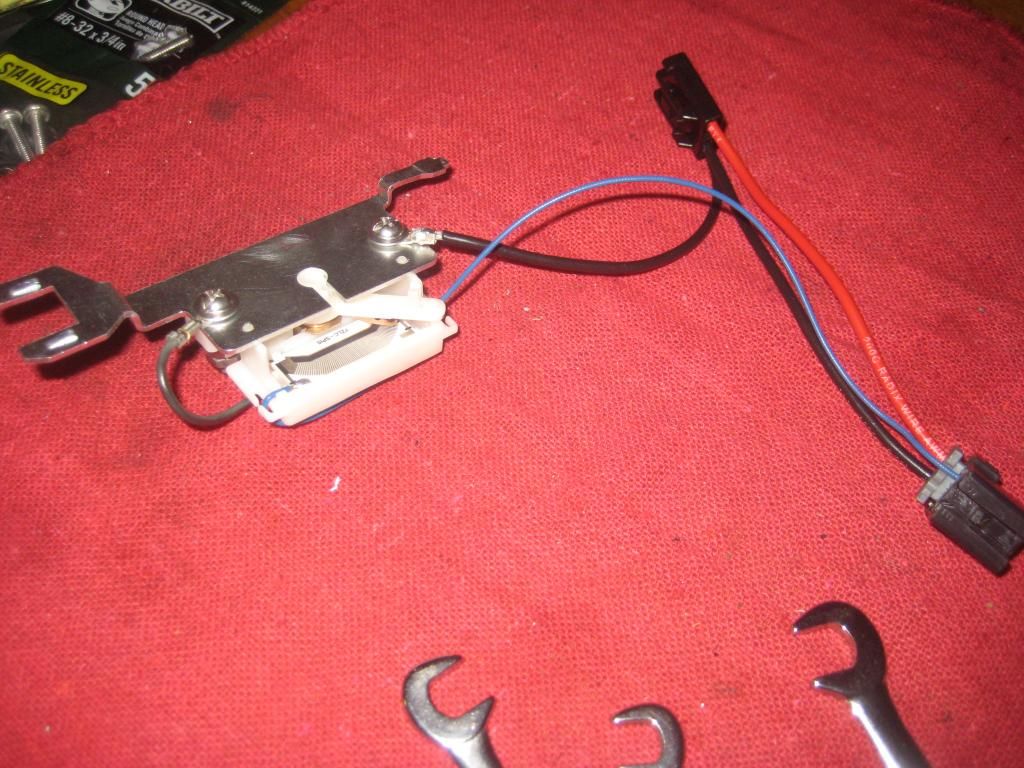
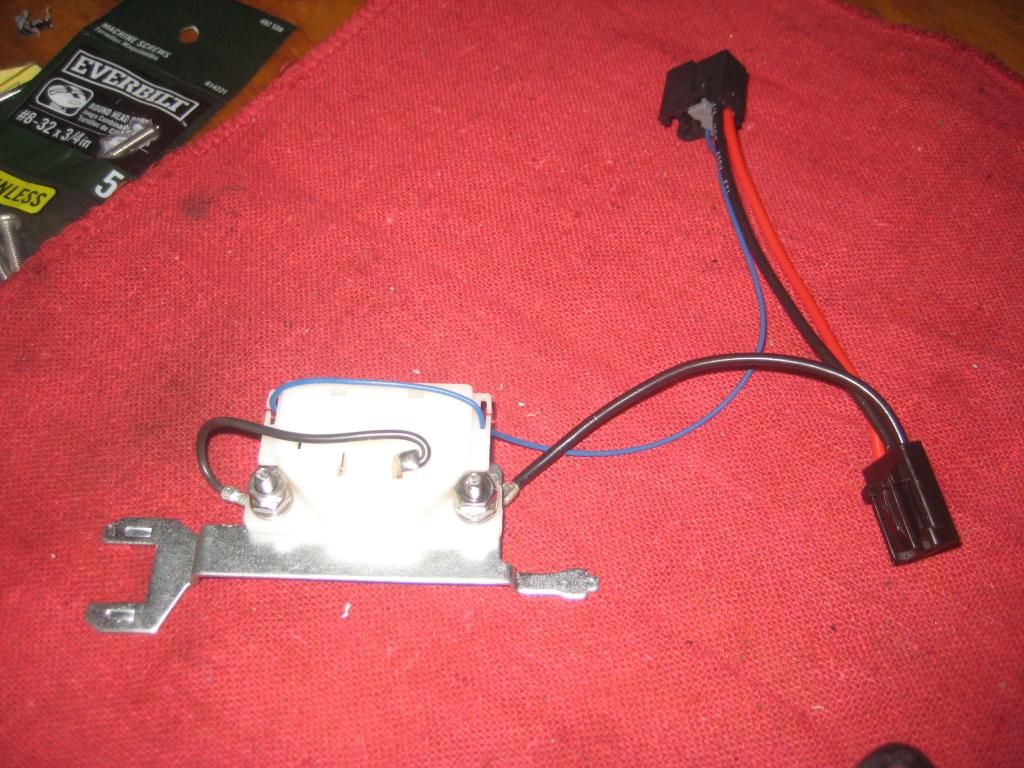
Once it was put back together, it was then mounted back to the Plastic Pump Housing and all was connected back up before installing back in the tank. As a test and before installing the SU/Fuel Pump assembly back in the tank, I connected the 3 wire harness and verified that the Cluster Gauge worked correctly and that I had good Ground and 12V to the Pump. A couple of pics of the whole unit before it went back in the tank
Hopefully this helps someone out that is also looking to replace their harness, FP or Refurbish the SU and has an aftermarket SU in the tank. I’m not certain, but I believe that GM has also changed their stock replacement part and it now uses a similar Float Assembly as the Spectra. So you may need to mod it in a similar fashion if using a stock type harness.
") .
. 

