

Welcome!
For my Roadmaster project I've had to dig into the wiper circuit design and theory of operation quite a bit. I wasn't able to find this info online and the Factory Service Manual, while good, left me wanting more detail, so I decided to dive in.
Below is the standard unit from most all B-Bodies as far as I know
![Image]()
![Image]()
Removing the black cover reveals a circuit board, cam, park relay and some of the gear train
![Image]()
![Image]()
If you remove the end of sweep cam, it looks like this underneath. It's hard to remove the clip without breaking the stud which kind of renders the whole cover assembly useless, so here is a picture so you don't have to break it")
![Image]()
Once the cam is off, you can remove the circuit board
![Image]()
![Image]()
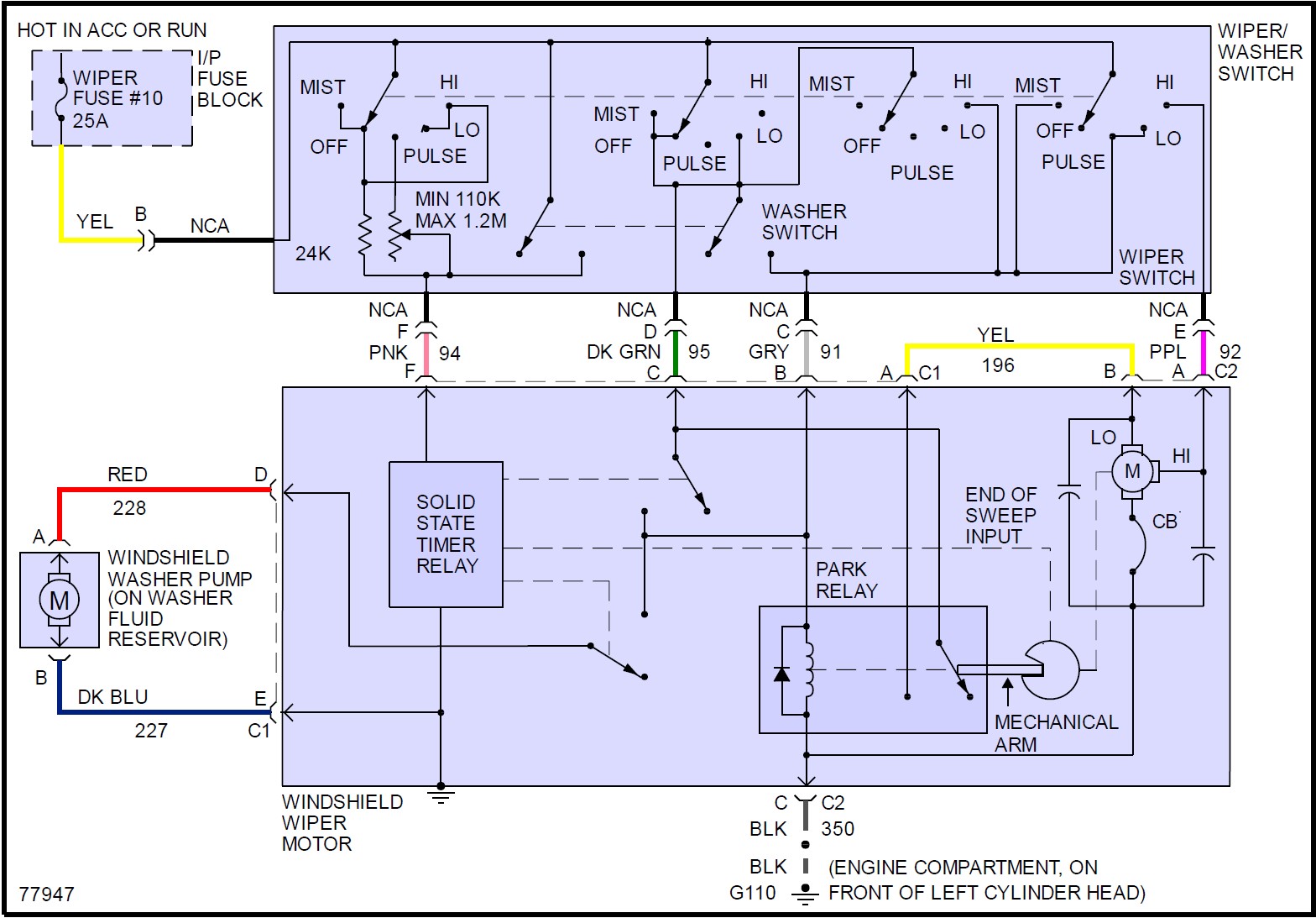
This is the schematic that you get from one of the online service manuals which is more/less the same as the Factory Service Manual (but easier to read in my opinion).
![Image]()
Here's the Factory version for comparison
![Image]()
The boxes in the above schematics that say "Solid State Relay" and "Park Relay" along with the text "End of Sweep Input" have a lot of little details in them that are not revealed in the above schematics. I created my own version of the schematics in a form kind of like a ladder diagram. I don't have access to a schematic drawing program so this is the best I could do with what I had. I'll update this someday if I get a software package to do so (Visio is my preferred tool for this kind of thing). The below is just the lower box that represents the wiper motor assembly only - it does not include the wiper stalk or anything inside the car
![Image]()
The park switch is a bit unique in it's operation. I took a video of it rather than trying to type out a dissertation of how it works...
More to come...
For my Roadmaster project I've had to dig into the wiper circuit design and theory of operation quite a bit. I wasn't able to find this info online and the Factory Service Manual, while good, left me wanting more detail, so I decided to dive in.
Below is the standard unit from most all B-Bodies as far as I know


Removing the black cover reveals a circuit board, cam, park relay and some of the gear train


If you remove the end of sweep cam, it looks like this underneath. It's hard to remove the clip without breaking the stud which kind of renders the whole cover assembly useless, so here is a picture so you don't have to break it

Once the cam is off, you can remove the circuit board


This is the schematic that you get from one of the online service manuals which is more/less the same as the Factory Service Manual (but easier to read in my opinion).
Here's the Factory version for comparison

The boxes in the above schematics that say "Solid State Relay" and "Park Relay" along with the text "End of Sweep Input" have a lot of little details in them that are not revealed in the above schematics. I created my own version of the schematics in a form kind of like a ladder diagram. I don't have access to a schematic drawing program so this is the best I could do with what I had. I'll update this someday if I get a software package to do so (Visio is my preferred tool for this kind of thing). The below is just the lower box that represents the wiper motor assembly only - it does not include the wiper stalk or anything inside the car

The park switch is a bit unique in it's operation. I took a video of it rather than trying to type out a dissertation of how it works...
More to come...


