

I recently had a coolant leak that seemed to be seeping up the 2nd Bolt back from the front on the driver Side. I know by design, this seems impossible but is the only explanation I could find and the evidence I found showed that.
No Leaks since it was replaced....See this thread.....
http://www.impalassforum.com/vBulle...4-engine-problems-maintenance/1308561-intake-manifold-gasket-replacement-s.html
Bolt showed signs of leakage and there was NO other area the leak was coming from. Anyway, this was my first time pulling an Intake off a LT1 engine and just wanted to share some pics and little tricks I found along the way to maybe help others.
The basics of the intake removal are straightforward and believe the Haynes manual walks you through these steps, so not going to cover each here. However, just some general observations, I did remove the Fuel rail/injectors first to gain a little better access to certain areas of the manifold. This also made it easier to get to the EGR valve and EGR Tube Nuts on the back of the Intake. I chose to remove the EGR before removal and install after the intake was on the car.
Once intake was removed, I also remove the Studs from the back of the intake so that it was MUCH easier to remove all the old gasket material from those areas. I’ll include a pic of those mount areas after cleanup. It’s easy to do if you just use 2 nuts on the stud and tighten them against each other. Then use a wrench on the nut closest to the intake to back out the stud. So much easier to do this than it is to clean around the Studs with a scraper.
I also noticed that the 2nd intake Bolt back on the passenger side that secures the Coolant metal tube seemed a little too long and doesn’t need to be. I really had to flex and lift up on this metal tube to get the bracket to clear the Stud. This Bolt has a nut on the end that secures the coolant tube to the intake, but after removal of the Nut, you got to lift it up a lot to get it to slide off. I’m sure this tube is pretty brittle and doing this also stresses the back Banjo bolt area too. So before reusing that bolt, I cut a good bit off the top so that there was just enough thread to slip the bracket over and secure the nut. Anything more than that seems useless and lifting more than needed could cause other repairs that could be difficult to get to at the back of the Heads.
When scraping the Heads and the end rails clean, be sure to lay something in the Lifter Valley and plug up the intake ports to keep debris out. This is pretty common knowledge by most. However, be sure that in the lifter valley you push the material back in and under the inner manifold bolt holes in the heads. These are wide open into the valley and any scrapings that fall thru these holes, could end up in the valley area and you may not see them. If your rags/blanket/whatever are tucked in there real well, nothing should get past it and slowly pull the edges of your cover over itself before removing from the valley area. A good idea to have a vacuum handy and visually inspect the valley area that nothing got past your cover. I also like to hit each intake port with the vacuum before pulling out the towels stuffed in there. Also, be sure to run a Tap down all the bolt holes to clean them up good. Keep in mind that those center bolt holes in the head just go into the lifter valley so have something below to catch the junk. Used a little compressed air to blow out debris from the 4 Corner Head Bolt areas that are just a closed off pocket.
When installing the intake, it is important that you “Drop” the intake manifold straight down onto the Heads/Block and not disturb the Gaskets or RTV. I’m a big guy but even this light Aluminum Intake can be a handful if you’re not careful. I tried a few dry runs before applying RTV and just did not feel confident that this would not get messed up. So, what to do? I got a cheap material Bolt, something easy to cut…think it was 3/8 - 16 thread and cut the head off and then cut 2 pieces about 1” long. So basically made 2 little all thread rods. Threaded each 1 into the front 2 holes of the Heads and left a little sticking up. The idea here is to use those on the front 2 holes as locator pins and while keeping the back of the manifold lifted slightly, then let the back end tilt down into place….worked like a Champ.
If doing this, keep in mind that the angle of the bolt holes combined with the intake will not allow you to have these stick up very far. What I did was cut them so short that none would stick above the intake manifold when installed. They were just threaded in finger tight but nothing to grab once the intake is installed. So I just took a HackSaw and cut a little slot on top of the end so I could use a Screwdriver to reach down inside of the Intake Bolt hole and unscrew the stud til I could grab it.
One last thing I did while the intake was removed was to beef up the Oil Pump Drive housing a little. I was going to get fancy and make something to surround the plastic but it’s a tight area up against the Block wall. Instead, I just went with a Flat Stainless Washer I had laying around.
My only regret, I didn’t have more time to clean up and Paint the intake manifold. But if I could offer any other advice to hopefully prevent leaks/problems….take your time and CLEAN EVERYTHING. I took each bolt, placed it in a vice and Wire brushed the threads, hit them with brake clean and then applied the correct PTFE Paste to the threads. Clean the Heads and the end rails very well too as well as the intake rails and wipe it all down. Run your finger over the flat surfaces and remove any burrs. The intake manifold had 2 little bumps/burrs on the edge that I found and I lightly hit them with a file to remove the burrs.
Torque the bolts to the correct spec and believe the number I had was 34 foot Pounds. So following the torque sequence pattern, I took them down to about 20 on the first pass and then again down to 34. I will re-check torque after a few more hot/cold cycles.
That’s about it…HTH someone.
Pic1 = Intake bolts laid out in order and 2 bolt back on right is where it "seemed" to be leaking.
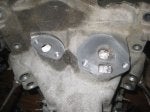
Pic2 = EGR Bosses on back of manifold all cleaned up and studs removed.
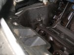
Pic3 = Washer used on Oil Pump Drive Plastic housing
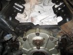
Pic4 = You can see the Dowels I made and the height they were at to let the manifold drop on. Any higher than than and the intake wont slip over these studs.
EDIT - Well slap me and call me Stupid. :>) I was just looking at the Intake Bolts in the pic and realize now, I could have just swapped the 2nd and 3rd bolts on the passenger side. That 3rd bolt is about the length I cut the 2nd bolt to.....Doh!! Of course I notice that now :>)
No Leaks since it was replaced....See this thread.....
http://www.impalassforum.com/vBulle...4-engine-problems-maintenance/1308561-intake-manifold-gasket-replacement-s.html
Bolt showed signs of leakage and there was NO other area the leak was coming from. Anyway, this was my first time pulling an Intake off a LT1 engine and just wanted to share some pics and little tricks I found along the way to maybe help others.
The basics of the intake removal are straightforward and believe the Haynes manual walks you through these steps, so not going to cover each here. However, just some general observations, I did remove the Fuel rail/injectors first to gain a little better access to certain areas of the manifold. This also made it easier to get to the EGR valve and EGR Tube Nuts on the back of the Intake. I chose to remove the EGR before removal and install after the intake was on the car.
Once intake was removed, I also remove the Studs from the back of the intake so that it was MUCH easier to remove all the old gasket material from those areas. I’ll include a pic of those mount areas after cleanup. It’s easy to do if you just use 2 nuts on the stud and tighten them against each other. Then use a wrench on the nut closest to the intake to back out the stud. So much easier to do this than it is to clean around the Studs with a scraper.
I also noticed that the 2nd intake Bolt back on the passenger side that secures the Coolant metal tube seemed a little too long and doesn’t need to be. I really had to flex and lift up on this metal tube to get the bracket to clear the Stud. This Bolt has a nut on the end that secures the coolant tube to the intake, but after removal of the Nut, you got to lift it up a lot to get it to slide off. I’m sure this tube is pretty brittle and doing this also stresses the back Banjo bolt area too. So before reusing that bolt, I cut a good bit off the top so that there was just enough thread to slip the bracket over and secure the nut. Anything more than that seems useless and lifting more than needed could cause other repairs that could be difficult to get to at the back of the Heads.
When scraping the Heads and the end rails clean, be sure to lay something in the Lifter Valley and plug up the intake ports to keep debris out. This is pretty common knowledge by most. However, be sure that in the lifter valley you push the material back in and under the inner manifold bolt holes in the heads. These are wide open into the valley and any scrapings that fall thru these holes, could end up in the valley area and you may not see them. If your rags/blanket/whatever are tucked in there real well, nothing should get past it and slowly pull the edges of your cover over itself before removing from the valley area. A good idea to have a vacuum handy and visually inspect the valley area that nothing got past your cover. I also like to hit each intake port with the vacuum before pulling out the towels stuffed in there. Also, be sure to run a Tap down all the bolt holes to clean them up good. Keep in mind that those center bolt holes in the head just go into the lifter valley so have something below to catch the junk. Used a little compressed air to blow out debris from the 4 Corner Head Bolt areas that are just a closed off pocket.
When installing the intake, it is important that you “Drop” the intake manifold straight down onto the Heads/Block and not disturb the Gaskets or RTV. I’m a big guy but even this light Aluminum Intake can be a handful if you’re not careful. I tried a few dry runs before applying RTV and just did not feel confident that this would not get messed up. So, what to do? I got a cheap material Bolt, something easy to cut…think it was 3/8 - 16 thread and cut the head off and then cut 2 pieces about 1” long. So basically made 2 little all thread rods. Threaded each 1 into the front 2 holes of the Heads and left a little sticking up. The idea here is to use those on the front 2 holes as locator pins and while keeping the back of the manifold lifted slightly, then let the back end tilt down into place….worked like a Champ.
If doing this, keep in mind that the angle of the bolt holes combined with the intake will not allow you to have these stick up very far. What I did was cut them so short that none would stick above the intake manifold when installed. They were just threaded in finger tight but nothing to grab once the intake is installed. So I just took a HackSaw and cut a little slot on top of the end so I could use a Screwdriver to reach down inside of the Intake Bolt hole and unscrew the stud til I could grab it.
One last thing I did while the intake was removed was to beef up the Oil Pump Drive housing a little. I was going to get fancy and make something to surround the plastic but it’s a tight area up against the Block wall. Instead, I just went with a Flat Stainless Washer I had laying around.
My only regret, I didn’t have more time to clean up and Paint the intake manifold. But if I could offer any other advice to hopefully prevent leaks/problems….take your time and CLEAN EVERYTHING. I took each bolt, placed it in a vice and Wire brushed the threads, hit them with brake clean and then applied the correct PTFE Paste to the threads. Clean the Heads and the end rails very well too as well as the intake rails and wipe it all down. Run your finger over the flat surfaces and remove any burrs. The intake manifold had 2 little bumps/burrs on the edge that I found and I lightly hit them with a file to remove the burrs.
Torque the bolts to the correct spec and believe the number I had was 34 foot Pounds. So following the torque sequence pattern, I took them down to about 20 on the first pass and then again down to 34. I will re-check torque after a few more hot/cold cycles.
That’s about it…HTH someone.
Pic1 = Intake bolts laid out in order and 2 bolt back on right is where it "seemed" to be leaking.
Pic2 = EGR Bosses on back of manifold all cleaned up and studs removed.
Pic3 = Washer used on Oil Pump Drive Plastic housing
Pic4 = You can see the Dowels I made and the height they were at to let the manifold drop on. Any higher than than and the intake wont slip over these studs.
EDIT - Well slap me and call me Stupid. :>) I was just looking at the Intake Bolts in the pic and realize now, I could have just swapped the 2nd and 3rd bolts on the passenger side. That 3rd bolt is about the length I cut the 2nd bolt to.....Doh!! Of course I notice that now :>)

") . I used a little dab of Ultrablack on the corners, then snapped in the side gaskets and then the bead along the rails and up the side about an inch and then let it sit for a few minutes before the BIG Drop.
. I used a little dab of Ultrablack on the corners, then snapped in the side gaskets and then the bead along the rails and up the side about an inch and then let it sit for a few minutes before the BIG Drop. 

