
Replacing the original Auxiliary Battery Post (ABP)
If your car has weird electrical problems for which you can’t find the cause, check to see if your ABP is made of zinc instead of brass. The zinc ones are silvery colored. GM used zinc for the ABP for some B-Body cars, but zinc wasn’t able to stand up to the power requirements. There is a Technical Service Bulletin (TSB 43-81-48, dated January 4, 1995) for the replacement of the zinc post with brass post.
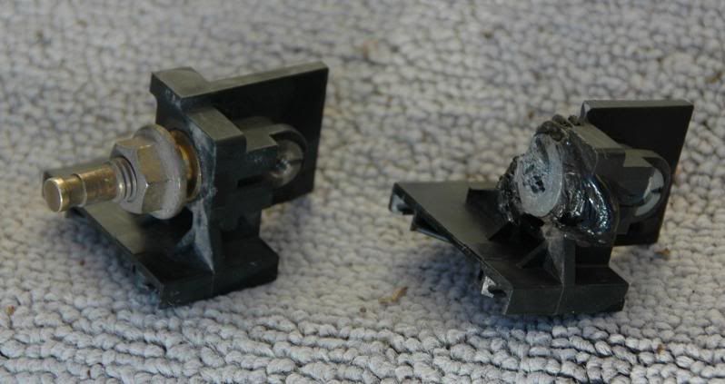
They actually get so hot that they melt. See the picture of the post that came out of Nick Danger’s car. This is known as a “thermal incident.”
![Image]()
Nick Danger’s ABP. You can see that the metal is pitted and the plastic has melted away all around the post. The back side is just as bad.
If you haven’t replaced your zinc APB, it’s a problem that’s just waiting to happen.
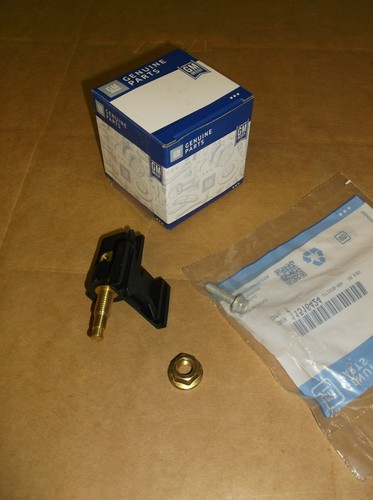
Part Numbers:
Connector (ABP assembly) - 12176639 (#7 in below schematic)
Bolt - 11516424 (#6 in below schematic)
Nut (brass) - 11505989 (much taller than original nut - not shown in schematic below – it is shown in the battery cable schematic on page 480 of the link below. It's at "Electrical > Battery Cable, Related Parts" on the index. )
A brass post can sometimes be found in junkyards, or you can buy it new from Focuztech.
http://www.focuztech.com/brass-aux-battery-post-for-impala-ss-and-caprice-fuse-box.html
The total cost was $40 (connector - $29, nut - $5, bolt $4 & tax): cheap insurance for these classic cars.
What looked like a simple fifteen minute R&R turned into almost a two hour job for a couple of rookies. Hopefully, these instructions will help fellow enthusiasts save some time and frustration. GM didn't optimize the service procedure for this job. It's really pretty simple if you know what steps are required.
You may not need to replace the bolt #6 but gep10 didn't want to shortcut anything. His zinc post got to hot to touch after just one start and showed evidence of overheating. The new beefier nut is called out in the current 1994 positive battery cable schematic; this is not the same nut from the zinc ABP (1994 model). The bolt appeared to be the same.
ABP REMOVAL.
![Image]()
(Page 497 of the online parts manual. It's "Electrical > Convenience Center, Engine Compartment" in the index. Thanks to the 9c1 forum.)
First step: Disconnect the positive battery cable (8mm) & secure out of the potential contact area at the battery terminal (wrapping in a shop towel works).
The ABP is attached to the fusebox on the passenger-side fender.
Remove the protective ABP cover #8.
Remove the nut on the ABP (15mm) and pull the battery cable off.
Remove the horizontal bolt #6 (10mm) that threads into the ABP. Notice that the two plates #9 and #10 are attached to this bolt. Removing the bolts will allow you to remove plates #9 and #10. The original ABP can not be removed until these plates are removed.
Remove the fuse block cover #1.
Remove the two 60 Amp fuses and the one or two 40 Amp fuses.
Remove the top fuse block #13 from the case #11, which is bolted to the inner fender. Do this by pushing out on the spring clips between #11 and #13. Pull #13 up and out of #11.
Remove the terminal lock #15.
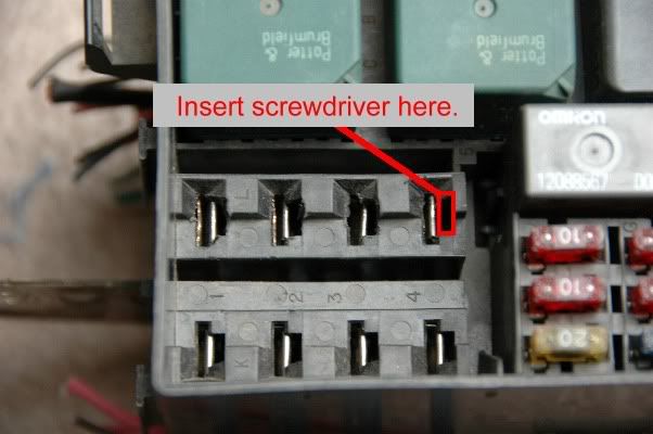
Plates #9 and #10 are held onto the fuse block #13 with small retaining clips. They are accessed from the top of the fuse block. It’s obvious which row has the plates underneath. Use a very small blade jeweler’s screwdriver (or even a bobby pin) to push down into the slot. You must push into the notch next to the slot that holds the blade of the fuse. Angle the screwdriver out to release the catch.
![Image]()
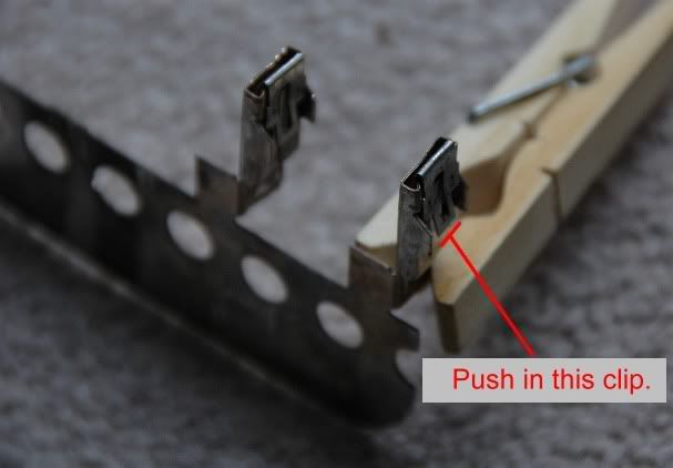
This is what the plates look like after they’ve been removed from the fuse block.
![Image]()
Remove plates #9 and #10 from the fuse block #13 by pulling them straight down from the bottom. The round holes are handy to insert a screwdriver into to help pull #9 and #10 out.
Gep10 and his son cleaned up both plates with 80 grit sandpaper and reused them; one of the plates had evidence of overheating so they polished that back to the brass finish. They also polished the battery terminal end with 80 grit sandpaper. Nick just reused the plates as they were.
Slide the old ABP #7 off of the fuse block #13.
ABP INSTALLATION.
Install the new brass ABP #7. It slides up the vertical tracks on #13.
Slide plates #9 and #10 into the bottom of the fuse block #13. Make sure all four terminals click into place and are secure. Test by pulling on the bottom side of 9 & 10.
Install bolt #6 through the holes of both terminal ends #9 and #10 and then screw it into ABP #7.
Install terminal lock #15.
Insert the fuse block #13 back into #11. Listen for the latches to click.
Install the battery cable over the ABP #7.
Install the ABP nut (Not shown on the above schematic – it is shown in the positive battery cable schematic on page 480. In the index it can be found at "Electrical > Battery Cable, Related Parts.").
Install the 40 and 60 amp fuses.
Install fuse box cover #1.
Place the protective cover #8 back over the ABP post.
Attach the positive battery cable to the battery.
Turn the ignition key to run & inspect gauges/radio/light function. If everything checks, start engine. You should be good to go.
--------------------------------------
Thanks again for everyone's help in sorting out this annoying and potentially dangerous issue
Hopefully this helps anyone who needs to do this. I think it can be done in 15 - 20 minutes following these instructions (certainly in a lot less time than I took). It is pretty easy to do once you know the procedure. These steps worked for us; you may come up with an alternative that works better.
Written by gep10 and Nick Danger. Thanks for assistance from fbi9c1 and grandpa’s wagon.
If your car has weird electrical problems for which you can’t find the cause, check to see if your ABP is made of zinc instead of brass. The zinc ones are silvery colored. GM used zinc for the ABP for some B-Body cars, but zinc wasn’t able to stand up to the power requirements. There is a Technical Service Bulletin (TSB 43-81-48, dated January 4, 1995) for the replacement of the zinc post with brass post.
They actually get so hot that they melt. See the picture of the post that came out of Nick Danger’s car. This is known as a “thermal incident.”
Nick Danger’s ABP. You can see that the metal is pitted and the plastic has melted away all around the post. The back side is just as bad.
If you haven’t replaced your zinc APB, it’s a problem that’s just waiting to happen.
Part Numbers:
Connector (ABP assembly) - 12176639 (#7 in below schematic)
Bolt - 11516424 (#6 in below schematic)
Nut (brass) - 11505989 (much taller than original nut - not shown in schematic below – it is shown in the battery cable schematic on page 480 of the link below. It's at "Electrical > Battery Cable, Related Parts" on the index. )
A brass post can sometimes be found in junkyards, or you can buy it new from Focuztech.
http://www.focuztech.com/brass-aux-battery-post-for-impala-ss-and-caprice-fuse-box.html
The total cost was $40 (connector - $29, nut - $5, bolt $4 & tax): cheap insurance for these classic cars.
What looked like a simple fifteen minute R&R turned into almost a two hour job for a couple of rookies. Hopefully, these instructions will help fellow enthusiasts save some time and frustration. GM didn't optimize the service procedure for this job. It's really pretty simple if you know what steps are required.
You may not need to replace the bolt #6 but gep10 didn't want to shortcut anything. His zinc post got to hot to touch after just one start and showed evidence of overheating. The new beefier nut is called out in the current 1994 positive battery cable schematic; this is not the same nut from the zinc ABP (1994 model). The bolt appeared to be the same.
ABP REMOVAL.

(Page 497 of the online parts manual. It's "Electrical > Convenience Center, Engine Compartment" in the index. Thanks to the 9c1 forum.)
First step: Disconnect the positive battery cable (8mm) & secure out of the potential contact area at the battery terminal (wrapping in a shop towel works).
The ABP is attached to the fusebox on the passenger-side fender.
Remove the protective ABP cover #8.
Remove the nut on the ABP (15mm) and pull the battery cable off.
Remove the horizontal bolt #6 (10mm) that threads into the ABP. Notice that the two plates #9 and #10 are attached to this bolt. Removing the bolts will allow you to remove plates #9 and #10. The original ABP can not be removed until these plates are removed.
Remove the fuse block cover #1.
Remove the two 60 Amp fuses and the one or two 40 Amp fuses.
Remove the top fuse block #13 from the case #11, which is bolted to the inner fender. Do this by pushing out on the spring clips between #11 and #13. Pull #13 up and out of #11.
Remove the terminal lock #15.
Plates #9 and #10 are held onto the fuse block #13 with small retaining clips. They are accessed from the top of the fuse block. It’s obvious which row has the plates underneath. Use a very small blade jeweler’s screwdriver (or even a bobby pin) to push down into the slot. You must push into the notch next to the slot that holds the blade of the fuse. Angle the screwdriver out to release the catch.
This is what the plates look like after they’ve been removed from the fuse block.
Remove plates #9 and #10 from the fuse block #13 by pulling them straight down from the bottom. The round holes are handy to insert a screwdriver into to help pull #9 and #10 out.
Gep10 and his son cleaned up both plates with 80 grit sandpaper and reused them; one of the plates had evidence of overheating so they polished that back to the brass finish. They also polished the battery terminal end with 80 grit sandpaper. Nick just reused the plates as they were.
Slide the old ABP #7 off of the fuse block #13.
ABP INSTALLATION.
Install the new brass ABP #7. It slides up the vertical tracks on #13.
Slide plates #9 and #10 into the bottom of the fuse block #13. Make sure all four terminals click into place and are secure. Test by pulling on the bottom side of 9 & 10.
Install bolt #6 through the holes of both terminal ends #9 and #10 and then screw it into ABP #7.
Install terminal lock #15.
Insert the fuse block #13 back into #11. Listen for the latches to click.
Install the battery cable over the ABP #7.
Install the ABP nut (Not shown on the above schematic – it is shown in the positive battery cable schematic on page 480. In the index it can be found at "Electrical > Battery Cable, Related Parts.").
Install the 40 and 60 amp fuses.
Install fuse box cover #1.
Place the protective cover #8 back over the ABP post.
Attach the positive battery cable to the battery.
Turn the ignition key to run & inspect gauges/radio/light function. If everything checks, start engine. You should be good to go.
--------------------------------------
Thanks again for everyone's help in sorting out this annoying and potentially dangerous issue
Hopefully this helps anyone who needs to do this. I think it can be done in 15 - 20 minutes following these instructions (certainly in a lot less time than I took). It is pretty easy to do once you know the procedure. These steps worked for us; you may come up with an alternative that works better.
Written by gep10 and Nick Danger. Thanks for assistance from fbi9c1 and grandpa’s wagon.
")